Monday, November 18, 2013

Optimizing the Ring Parameters

Optimizing the Ring Parameters

After the molds were completely machined, we moved on to shoot out a few test parts from the injection molding machine. We did 4 iterations with different parameters to determine which parameters we would use for the final production run.

Test 1:


The very first trial piece had a very noticeable weld line (not obvious from the picture, but it can be seen right across the "#1" marker) as well some considerable dishing around the center triangle. The cause for both defects was a shortage of injection pressure as well as injection speed. The weld lines form because the plastic cools and hardens before the streams of molten material are able to fuse together properly. The dishing is caused by a lack of material towards the center of the ring because plastic is not being packed sufficiently before cooling takes place.

First Trial

Test 2:


For this trial, we increased the injection speed profile to get rid of the huge weld line formed during the first trial run. It was effective in that the weld line is not so obvious but it can be seen and felt with a little more close attention. Dishing was still a problem.

Second Trial

Test 3:


For this trial, we increased the injection pressure to address the dishing in the center of the ring. By bumping up the pressure, we allow more molten plastic to be packed into the mold before it gets a chance to cool therefore the mold will be filled with plastic and no dishing will appear. It worked to a certain degree in that it improved the dishing problem, but we still could do better. 

Third Trial

Test 4:


At this point, we were not able to increase the injection pressure any further but what we did was increased the stroke speed so that material could flow in a bit faster. This solution improved the dishing problem significantly but there still was some left. Unfortunately that was all that we could optimize for and overall we have agreed to use the latest set of parameters during our production runs.

Fourth Trial

The complete set of optimized parameters can be found here.

Wednesday, November 6, 2013

Soldered Circuit in Thermoform testing

Current Circuit Status:  Working!  Fits in thermoform!  Just trying to improve assembly/solder time and write up some work instructions now.  But the tests worked great!  Actually, in the first test one of the contacts between the LEDs and battery came loose and only 2 of 3 LEDs were lit.  The issue was corrected for the second video, but I'm really bad at yo-yo.


Thursday, October 31, 2013

First Thermoformed and Injection-Molded Pieces!

Last Thursday we made our first thermoform and injection molded pieces! Dave taught us how to use the machines and we now have our first couple of test pieces for the thermo-window and the snap ring. 

Thermoforming the Window:

Before using the thermoform machine, vacuum holes had to be made on the thermo-window die. 
Carefully making vacuum holes on the die.
Did I have to stand on a stool to reach? Maybe. . .  
Once the holes were made, Dave taught us how to use the thermoform machine, which was relatively easy to understand. A video showing the process is shown below. The scary part of the whole process is the really loud sound the clamp makes when it engages. 


Three different trials were run using the clear thermoform material. During each trial, I tried to increase definition of the piece made in order for it to flush well with the ring piece. 

The team watched the first couple of trials together.
One of the perks of being short and not being able to see
what the machine is doing is getting to use the step ladder. ;)

Injection Molding the Ring:


Daivon learning how to use the injection mold machine.

Elyud collects parameters for each trial run. 
  
An injection molded ring piece
(Note: color shown is not the color to be used.)
We ran a couple of trials for the injection molded piece, changing different parameters in order to get rid of the weld line and reduce dishing on the piece.

Conclusions:

At the end of our lab time, we were satisfied with our first couple of trials. We recorded the parameters used for each trial, taking note of what worked and what didn't. As you can see below, our first two pieces fit well with each other! I was initially worried I would have to re-machine the thermo-window die because I had forgotten to fillet each island, but it turns out it didn't really make a difference. Even though the thermo-window piece features were well defined at the end of the part making trial, it fit well with the ring. 

Fitting the injection molded ring to the thermo-window.
And now I present you all with our "Awkward Dance." It all started with Daivon while we waited for our turn to use the machines. . . We either did that, or like Amelia and Daivon are doing in the picture below, we looked out of the windows in the shop. . .


Till next time! 

Monday, October 21, 2013

An Insider Scoop: The Ring Mold

The ring piece of our yo-yo was designed based on the Iron Man model of the mark IV arc reactor, but we decided to change it a little to make it our own: We added studs to the outermost diameter and tweaked the middle geometry for easier injection molding. 
Google Image of the Mark IV 
As discussed in previous posts, the ring of our yoyo will be an injection molded part. Therefore it is necessary to have two molds that act as a cavity and core to obtain the necessary features in the injection molding process. Most of the visible features of the ring will be due to the contours of the core mold while the cavity mold provides a necessary depth equal to the thickness of the ring. Below we describe the design and manufacturing plans for the both the cavity and the core molds.

The CORE MOLD


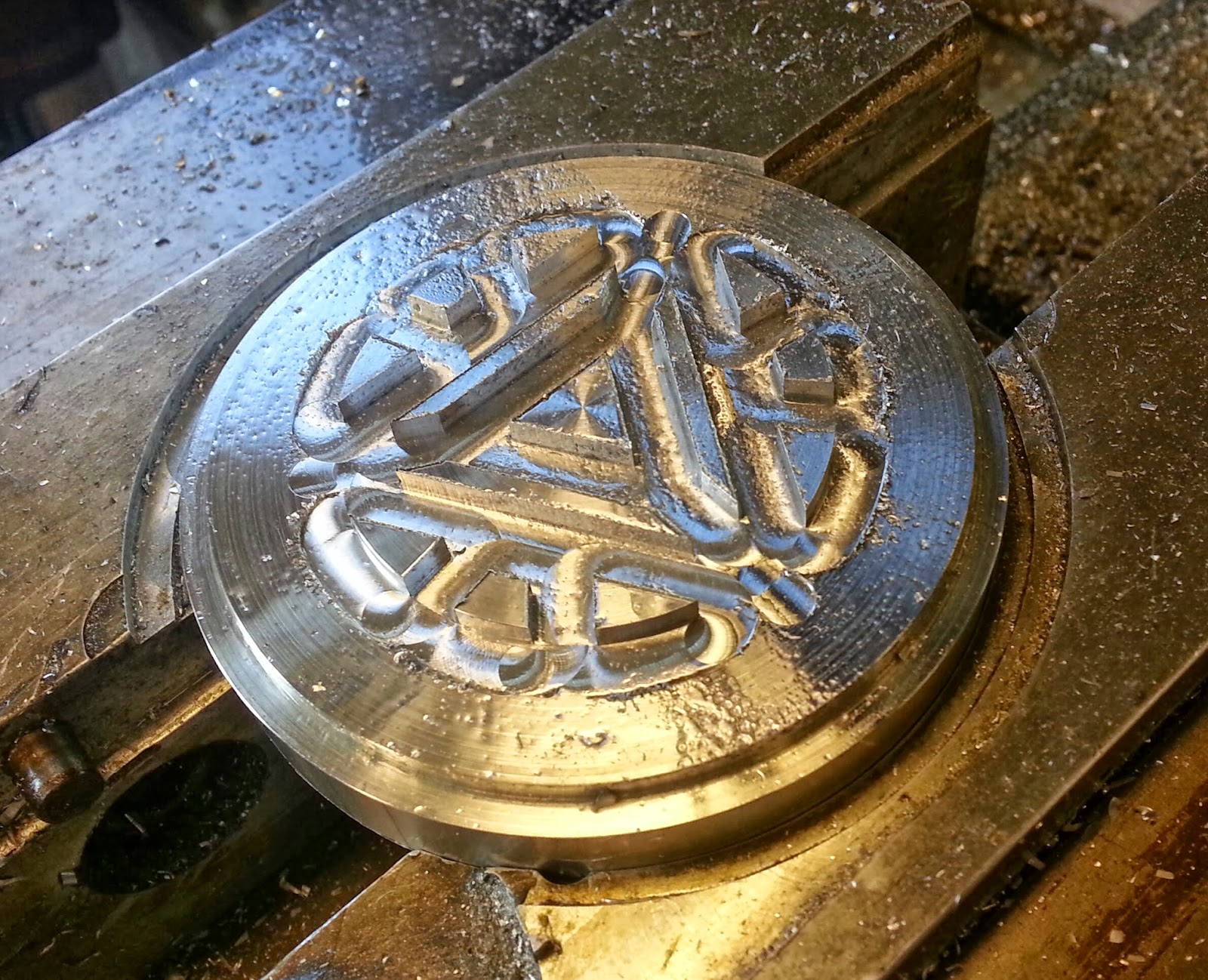
Fig: The core mold houses the major aesthetic features of the ring

Dimensions on the core mold

The dimensions of the contours of the core mold are the same as what we originally designed the ring to be like. We need not calculate any shrinkage allowances in the core mold because during the injection molding process, the plastic is going to shrink around these contours, filling up the open spaces in between the islands. We allow for shrinkage in the cavity mold design because it determines our outer diameter of the ring, which will be affected by shrinkage. You can see how we accounted for shrinkage when we describe the cavity mold design later.

The Machining Process

The entire machining operation for the core mold will be performed in the EZ-trak mill. We flirted with the idea of using the lath first to face off a bulk of the material then transfer to the mill, which would save us a few minutes of machining time. But we decided against it because ultimately the saved time would be compensated by the time it would take to transfer the mold blank from the lath to the mill, as well us variations in the two different machines could lead to wrong final dimensions in our mold.

The complete process plan for machining this mold can be found here.

The CAVITY MOLD

Cavity Mold in masterCAM
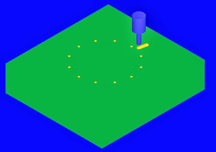
Stud holes and runner


Dimensions on the Cavity Mold

The outer diameter had to be chosen to account for shrinkage of plastic around the core islands. To calculate the amount of shrinkage, we took an average of about the outer diameters of 10 rings previously injection molded that match our specifications. Then we measured the outer diameter of the cavity mold used in the injection molding process that produced those rings and we found the shrinkage to be about 1.4%. Daivon and I think the outer diameter would be the biggest thing we will be checking for during our testing run. Well, that and the awesome holes we drilled into the cavity for the studs on the outside of the ring! During manufacturing we noticed that the holes are quite small. It might be difficult to fit plastic into them. After the testing runs we might have to enlarge them a bit.

Machining Process

The bore of the cavity will be machined in the lathe. It is a simple roughing and finishing cycle that didn't take more than 2 minutes. Then the holes for the studs will be drilled in the CNC mill.  

The complete process plan for machining this mold can be found here.


1.5" diameter facing tool


On to the 0.5" pocketing

Peck drill for ejection pins


That's one truly broken tool bit


Elyud got chips all under his shoes for all his troubles

Daivon is clearly unhappy about it!
But after two broken tool bits, one complete redo and lots and lots of laughter, we finished both our molds and they look as lovely as ever!!!

Finally a beautifully completed core mold


Just as beautiful cavity mold


Mold Machining: Day 1

This past Thursday was extremely eventful for the team! We started making molds for some of our pieces and even accidentally broke some tool pieces along the way (okay, maybe three. . . ).

Elyud and Daivon preparing to mill one of their Ring piece molds.
Check out those safety glasses!

Here is a video Dave, our lab instructor, helped me take while using the lathe machine for the die of our Thermo-Window. We were able to capture some of the chip action!


An important thing the team learned before machining is that there is no reason a mold should only be made using just the milling or lathe machine. As it turns out, using both machines to create a mold makes the machining process so much faster and efficient. For example, for the thermoform 'window' mold of our yo-yo, the time to manufacture was reduced from an estimated time of 70 minutes to 12 minutes! It was originally going to be made using only the milling machine, but after checking the files with Dave, he suggested we use the lathe as well. 

Thermo-Window Die. Machined with the lathe and then the mill. 
Even though using both the lathe and the mill to machine the Thermo-Window die has many benefits, a minor issue I encountered was that it can be tricky to align the already lathed piece's surface for the milling machine. As can be seen in the picture above, the surface is not completely smooth around each island of the die even though all cuts were supposed to be made to the same depth. Although this does not seem to cause any immediate problem for us now, one way we could have fixed that was to zero the surface on the milling machine to account for the alterations caused by the lathe. 

Left: Elyud, Daivon, and I wait for our pieces to finish machining. Right: Adding pin holes to thermo-form die.

One of the molds for the Ring with a broken tool bit above it. . .

Super Happy Thuan with a finished Body mold. 
Some of our finished molds. Top and Bottom molds are for the cavity. Middle piece is the thermo-form die for the window piece. 
Apart from the issues we ran into with the mill, all in all, it was a very successful day. Our next steps: finish our molds and begin manufacturing yo-yo pieces!! Stay tuned!

You can take a look at the process plan for each mold and our estimated manufacturing time here. 

Saturday, October 12, 2013

Circuitry Testing

UPDATE: Testing the circuit on with two tilt ball switches taped to a yo yo.


WORKS.


Orientation testing of the circuit on a breadboard.

Rotational motion testing of the circuit.