Thursday, October 31, 2013

First Thermoformed and Injection-Molded Pieces!

Last Thursday we made our first thermoform and injection molded pieces! Dave taught us how to use the machines and we now have our first couple of test pieces for the thermo-window and the snap ring. 

Thermoforming the Window:

Before using the thermoform machine, vacuum holes had to be made on the thermo-window die. 
Carefully making vacuum holes on the die.
Did I have to stand on a stool to reach? Maybe. . .  
Once the holes were made, Dave taught us how to use the thermoform machine, which was relatively easy to understand. A video showing the process is shown below. The scary part of the whole process is the really loud sound the clamp makes when it engages. 


Three different trials were run using the clear thermoform material. During each trial, I tried to increase definition of the piece made in order for it to flush well with the ring piece. 

The team watched the first couple of trials together.
One of the perks of being short and not being able to see
what the machine is doing is getting to use the step ladder. ;)

Injection Molding the Ring:


Daivon learning how to use the injection mold machine.

Elyud collects parameters for each trial run. 
  
An injection molded ring piece
(Note: color shown is not the color to be used.)
We ran a couple of trials for the injection molded piece, changing different parameters in order to get rid of the weld line and reduce dishing on the piece.

Conclusions:

At the end of our lab time, we were satisfied with our first couple of trials. We recorded the parameters used for each trial, taking note of what worked and what didn't. As you can see below, our first two pieces fit well with each other! I was initially worried I would have to re-machine the thermo-window die because I had forgotten to fillet each island, but it turns out it didn't really make a difference. Even though the thermo-window piece features were well defined at the end of the part making trial, it fit well with the ring. 

Fitting the injection molded ring to the thermo-window.
And now I present you all with our "Awkward Dance." It all started with Daivon while we waited for our turn to use the machines. . . We either did that, or like Amelia and Daivon are doing in the picture below, we looked out of the windows in the shop. . .


Till next time! 

Monday, October 21, 2013

An Insider Scoop: The Ring Mold

The ring piece of our yo-yo was designed based on the Iron Man model of the mark IV arc reactor, but we decided to change it a little to make it our own: We added studs to the outermost diameter and tweaked the middle geometry for easier injection molding. 
Google Image of the Mark IV 
As discussed in previous posts, the ring of our yoyo will be an injection molded part. Therefore it is necessary to have two molds that act as a cavity and core to obtain the necessary features in the injection molding process. Most of the visible features of the ring will be due to the contours of the core mold while the cavity mold provides a necessary depth equal to the thickness of the ring. Below we describe the design and manufacturing plans for the both the cavity and the core molds.

The CORE MOLD


Fig: The core mold houses the major aesthetic features of the ring

Dimensions on the core mold

The dimensions of the contours of the core mold are the same as what we originally designed the ring to be like. We need not calculate any shrinkage allowances in the core mold because during the injection molding process, the plastic is going to shrink around these contours, filling up the open spaces in between the islands. We allow for shrinkage in the cavity mold design because it determines our outer diameter of the ring, which will be affected by shrinkage. You can see how we accounted for shrinkage when we describe the cavity mold design later.

The Machining Process

The entire machining operation for the core mold will be performed in the EZ-trak mill. We flirted with the idea of using the lath first to face off a bulk of the material then transfer to the mill, which would save us a few minutes of machining time. But we decided against it because ultimately the saved time would be compensated by the time it would take to transfer the mold blank from the lath to the mill, as well us variations in the two different machines could lead to wrong final dimensions in our mold.

The complete process plan for machining this mold can be found here.

The CAVITY MOLD

Cavity Mold in masterCAM
Stud holes and runner


Dimensions on the Cavity Mold

The outer diameter had to be chosen to account for shrinkage of plastic around the core islands. To calculate the amount of shrinkage, we took an average of about the outer diameters of 10 rings previously injection molded that match our specifications. Then we measured the outer diameter of the cavity mold used in the injection molding process that produced those rings and we found the shrinkage to be about 1.4%. Daivon and I think the outer diameter would be the biggest thing we will be checking for during our testing run. Well, that and the awesome holes we drilled into the cavity for the studs on the outside of the ring! During manufacturing we noticed that the holes are quite small. It might be difficult to fit plastic into them. After the testing runs we might have to enlarge them a bit.

Machining Process

The bore of the cavity will be machined in the lathe. It is a simple roughing and finishing cycle that didn't take more than 2 minutes. Then the holes for the studs will be drilled in the CNC mill.  

The complete process plan for machining this mold can be found here.


1.5" diameter facing tool


On to the 0.5" pocketing

Peck drill for ejection pins


That's one truly broken tool bit


Elyud got chips all under his shoes for all his troubles

Daivon is clearly unhappy about it!
But after two broken tool bits, one complete redo and lots and lots of laughter, we finished both our molds and they look as lovely as ever!!!

Finally a beautifully completed core mold


Just as beautiful cavity mold


Mold Machining: Day 1

This past Thursday was extremely eventful for the team! We started making molds for some of our pieces and even accidentally broke some tool pieces along the way (okay, maybe three. . . ).

Elyud and Daivon preparing to mill one of their Ring piece molds.
Check out those safety glasses!

Here is a video Dave, our lab instructor, helped me take while using the lathe machine for the die of our Thermo-Window. We were able to capture some of the chip action!


An important thing the team learned before machining is that there is no reason a mold should only be made using just the milling or lathe machine. As it turns out, using both machines to create a mold makes the machining process so much faster and efficient. For example, for the thermoform 'window' mold of our yo-yo, the time to manufacture was reduced from an estimated time of 70 minutes to 12 minutes! It was originally going to be made using only the milling machine, but after checking the files with Dave, he suggested we use the lathe as well. 

Thermo-Window Die. Machined with the lathe and then the mill. 
Even though using both the lathe and the mill to machine the Thermo-Window die has many benefits, a minor issue I encountered was that it can be tricky to align the already lathed piece's surface for the milling machine. As can be seen in the picture above, the surface is not completely smooth around each island of the die even though all cuts were supposed to be made to the same depth. Although this does not seem to cause any immediate problem for us now, one way we could have fixed that was to zero the surface on the milling machine to account for the alterations caused by the lathe. 

Left: Elyud, Daivon, and I wait for our pieces to finish machining. Right: Adding pin holes to thermo-form die.

One of the molds for the Ring with a broken tool bit above it. . .

Super Happy Thuan with a finished Body mold. 
Some of our finished molds. Top and Bottom molds are for the cavity. Middle piece is the thermo-form die for the window piece. 
Apart from the issues we ran into with the mill, all in all, it was a very successful day. Our next steps: finish our molds and begin manufacturing yo-yo pieces!! Stay tuned!

You can take a look at the process plan for each mold and our estimated manufacturing time here. 

Saturday, October 12, 2013

Circuitry Testing

UPDATE: Testing the circuit on with two tilt ball switches taped to a yo yo.


WORKS.


Orientation testing of the circuit on a breadboard.

Rotational motion testing of the circuit.

Thursday, October 10, 2013

Learning Moment of the Week

We're really good at coming up with bad ideas.  Our first terribly great idea was really complicated designs (that are going to look awesome but currently...).  Then, when making the thermoform dies, we thought we would just mill the entire thing.  As we continued to work on our dies, we got stuck trying to reduce the time for the milling operations.  We got as high as 10 hours, and as low as 1.5.  But then, we talked to Dave.  It's amazing what people who know things can do!  We realized we could actually remove a lot of material on the lathe, and then go back and mill the fine details around our central design, especially because our designs are circular.  So we'll be turning in terrible timed dies for deliverable II, but should have tales of great improvement by the end of the weekend!

OFFICIAL LATE NIGHT WORK AWARDS

CURRENT ARC XV AWARDS
10/09 - Most Crashes of MasterCAM - Daivon and Elyud
10/09 - Best Machining time improvement (10 hrs to 25 min) - Morgan
10/17 - Most tool bits broken to date (2) - Daivon and Elyud

Tuesday, October 8, 2013

Circuit Design and Experimentation

One of the coolest things about the Arc Reactor is its characteristic glow - so we wanted to add this feature to our yo yo as well.

Component Breakdown

LEDS - We wanted the LEDs to be blue to best represent the Arc Reactor from movies.  The voltage drop across blue LEDs is significantly greater than across LEDs with a longer wavelength.  So we are looking at near a 3.3V drop from the LED.

SWITCH  - To activate the circuit when the yo yo is spinning, we looked at a couple of different types of switches.  

First, we looked at creating a mechanical system that would take advantage of the spinning motion of the yo yo to move a spring and close the circuit.  A similar design was used in a Make magazine project.  http://makezine.com/projects/led-yo-yo-side-caps/

Then, we looked at switches that are activated by motion.  
Mercury Switches - would work, but are going out of style for safety concerns
Vibration Switches - also would work, but might be too sensitive - we don't want it lighting up if you're just carrying the yo yo in your pocket
Tilt Ball Switches - this is what we decided to try.  When the yo yo spins, the internal ball will move and close the circuit, and the lights will go on.

BATTERY - We wanted something as small (and symmetrical) as possible.  Watch batteries fit these requirements well.  After diagramming and experiments, we decided to use 2 CR2012 watch batteries for each circuit.

Experimenting with LED, batteries, and math
After playing with different watch batteries, LEDs, and doing some circuit equations, we have determined that our circuit should work (in theory).  Just waiting for the actual components to arrive to double check!
Comparing one LED powered by 6v, to 3 LEDs in parallel with 3V

3 LEDs in parallel with 6V
Physically planning circuit

Playing with LED orientation
LEDs are brightest viewed from the top, but for assembly ease we wanted the LEDs to be on their side in the LED holder.  At 3V powering the circuit, the side view of the LED was very disappointing.  But at 6V, the glow was much better.  

With 3V

With 6V
  

Monday, October 7, 2013

Our Yo-Yo

The Project

As part of our Design and Manufacturing II class, our team has to design and manufacture a yoyo made of injection molded and thermoformed parts. The project is meant as an opportunity for student groups to apply their knowledge of CAD/CAM when designing and manufacturing, not only the yo-yos, but also the tools needed to make them. The goal is to help us learn how to determine the manufacturing rate, cost, quality, and flexibility of our product (and any other product or project we are involved with in the future!) in order to optimize our parameters for successful production of 50 yo-yos.

Design Requirements and Guidelines

To give a better understanding of the project and of the design constraints, here are some of the design requirements:

  • Yoyo should include 2 or 3 injection-molded parts and at least 1 thermoformed part.
  • Volume of each injection-molded part should not exceed 2.7 in3.
  • Clear High Impact polystyrene ‘HIPS’ sheet of 0.030” provided.
  • Max outside diameter of the injection-molded parts cannot exceed 2.5”.
  • Spec ranges must be specified for each of the critical dimensions of the components

Our Design

Our goal when choosing our design was for the product to be feasible to be manufactured, but at the same time we wanted a bit of a challenge. During our first meeting, we generated ideas that ranged from chicken, to Dave doing cartwheels, to Harry Potter themed yo-yos. We ended up with a design the entire team felt met our goal, but would also be aesthetically pleasing, had some flair, and would provide a bit of a challenge. These design characteristics were especially important, and we felt that it was necessary for us to make our design unique. For that reason, we decided to take the design for the Arc Reactor Mark V and tried to stay as true to the design as possible.


Each half of our yoyo is made of four parts we will machine and manufacture, not including the shim to weigh our yoyo for easier use or the circuitry needed for our yoyo to light up when spun

Exploded SolidWorks rendered view of the assembled yo-yo.
The injection-molded body is the largest and most critical part of our yoyo, as it serves as the housing and point of attachment for all of the other pieces. The ring is attached on an interference, or snap fit, and the window and circuit are press fitted into the body. It will also house a shim, which will possibly be ordered from McMaster-Carr, to add weight to the yoyo to improve its performance. Each yoyo will contain two body pieces that will be connected to one another at the center of each piece with a hex nut and bolt.

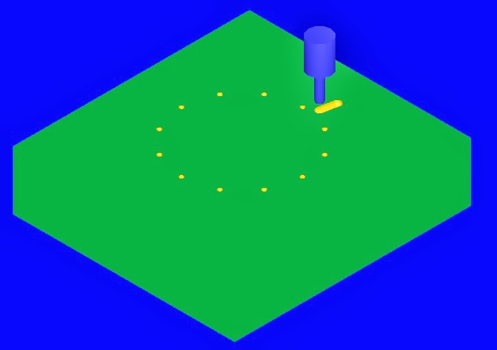
The ring is another critical component of the yoyo assembly. In addition to securing the inner parts through its snap fit with the body, it also houses the design of the arc-reactor, which is the inspiration for our yoyo. The ring will be made of plastic by injection-molding, and will attach to the body through an interference or snap fit. The relatively complex geometry will make the mold design a bit challenging, especially taking into consideration the fact that it is supposed to snap fit with the body. Therefore, paying close attention to required tolerances and amount of shrinkage during cooling is very important.

Ring piece geometry, front view.

The thermoformed window, as we like to call it, is a clear thermoformed piece that will fit into the negative space of the ring. It acts as a ‘window’ into the reactor and closes in all of the components of the yoyo. A high impact polystyrene sheet with thickness of .030” will be heated and formed onto a die that inversely mirrors the geometry of the ring piece and will then be press cut into the circular shape to fit into the body. An anticipated problem seen with this piece is achieving the sharp geometry needed to fit into the gaps of the ring, but that will be addressed if needed during the trail runs with different parameters. For the time being, the piece will be designed to line-fit with the ring piece.

The clear, thermoformed circuit component will be drape formed.  The clear material will allow the LEDs, battery, and switch to be seen through the assembly, adding to the Tony Stark-esque feel.  The components will need to be soldered and snapped into the thermoformed part after the part is made.  During assembly, the circuit assembly with holder will press fit into the bottom of the body, using the hex nut standoff as the main registration point.  Posts will also go from the bottom of the thermoformed part to the ring, adding a second level of security beyond the press fit.  The circuit assembly will then be pressed into the body, before the thermoformed window and snap ring.

Throughout the design process, our team made it a goal to make the product as streamlined to manufacture as possible in order to keep the rate of production high. The two parts of the yoyo that we foresee having the most difficulty with, the circuit piece and the clear window, were designed to be thermoformed. This will allow us much more flexibility further down the line to make quick design changes.  Additionally, we predict that the circuitry will be main bottleneck in our manufacturing and integration process, and as a result have designed it to be a subassembly. In contrast to that, the parts that will have the biggest effect on the aesthetics and feel of the yoyo were designed to be injection molded to ensure that the quality is high and consistent.

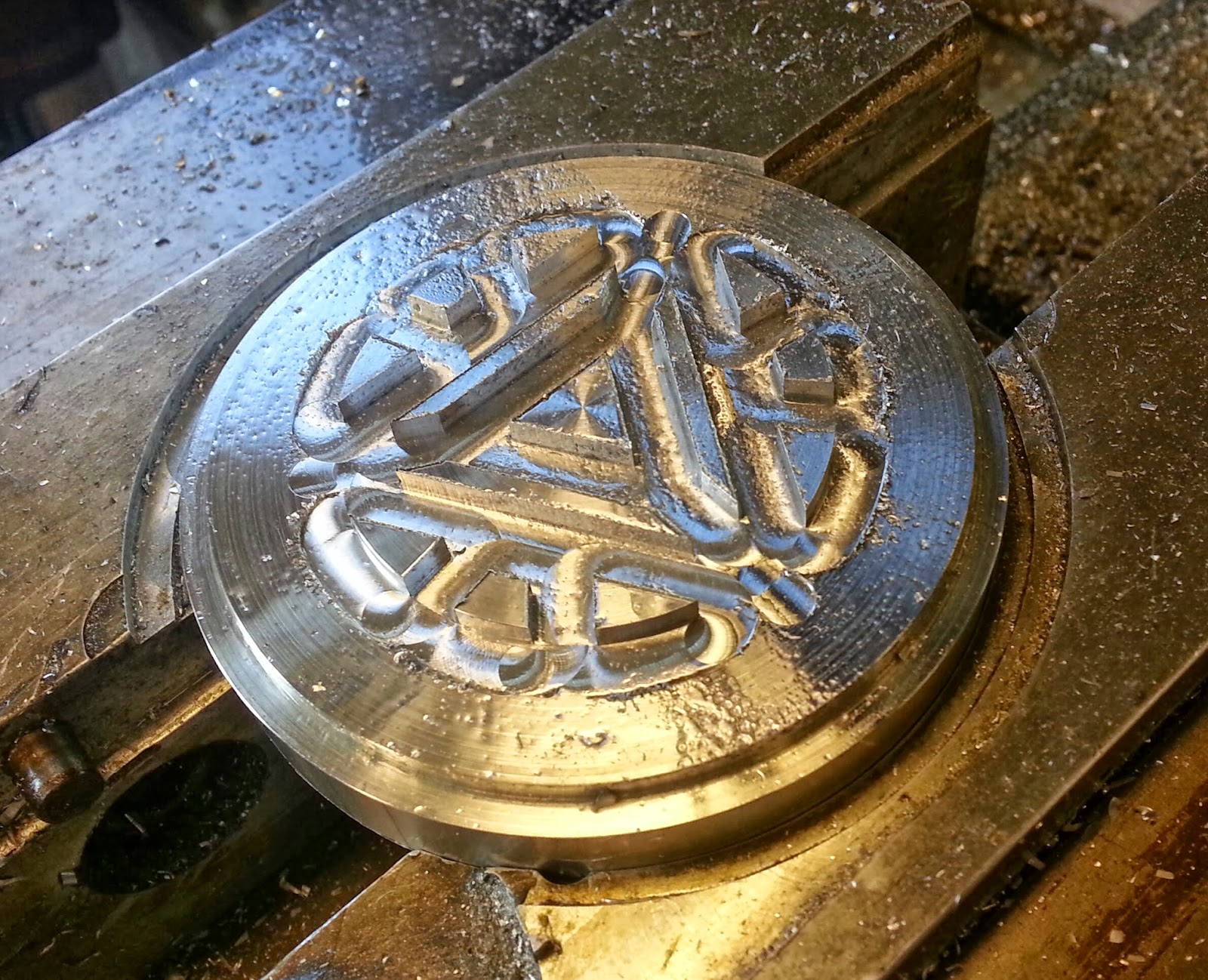
Arc Reactor Mark V Yo-Yo.

We are currently working on the mold drawings for our injection-molded pieces and die drawings for the thermo-formed parts. Stay tuned to learn more about our project and to see where it takes us!

You can view a full list of our design specifications here. 
View our proposed schedule here.