The ring piece of our yo-yo was designed based on the Iron Man model of the mark IV arc reactor, but we decided to change it a little to make it our own: We added studs to the outermost diameter and tweaked the middle geometry for easier injection molding.
 |
| Google Image of the Mark IV |
As discussed in previous posts, the ring of our yoyo will be an injection molded part. Therefore it is necessary to have two molds that act as a cavity and core to obtain the necessary features in the injection molding process. Most of the visible features of the ring will be due to the contours of the core mold while the cavity mold provides a necessary depth equal to the thickness of the ring. Below we describe the design and manufacturing plans for the both the cavity and the core molds.
The CORE MOLD
 |
| Fig: The core mold houses the major aesthetic features of the ring |
Dimensions on the core mold
The dimensions of the contours of the core mold are the same as what we originally designed the ring to be like. We need not calculate any shrinkage allowances in the core mold because during the injection molding process, the plastic is going to shrink around these contours, filling up the open spaces in between the islands. We allow for shrinkage in the cavity mold design because it determines our outer diameter of the ring, which will be affected by shrinkage. You can see how we accounted for shrinkage when we describe the cavity mold design later.
The Machining Process
The entire machining operation for the core mold will be performed in the EZ-trak mill. We flirted with the idea of using the lath first to face off a bulk of the material then transfer to the mill, which would save us a few minutes of machining time. But we decided against it because ultimately the saved time would be compensated by the time it would take to transfer the mold blank from the lath to the mill, as well us variations in the two different machines could lead to wrong final dimensions in our mold.
The complete process plan for machining this mold can be found
here.
The CAVITY MOLD
 |
| Cavity Mold in masterCAM |
 |
| Stud holes and runner |
Dimensions on the Cavity Mold
The outer diameter had to be chosen to account for shrinkage of plastic around the core islands. To calculate the amount of shrinkage, we took an average of about the outer diameters of 10 rings previously injection molded that match our specifications. Then we measured the outer diameter of the cavity mold used in the injection molding process that produced those rings and we found the shrinkage to be about 1.4%. Daivon and I think the outer diameter would be the biggest thing we will be checking for during our testing run. Well, that and the awesome holes we drilled into the cavity for the studs on the outside of the ring! During manufacturing we noticed that the holes are quite small. It might be difficult to fit plastic into them. After the testing runs we might have to enlarge them a bit.
Machining Process
The bore of the cavity will be machined in the lathe. It is a simple roughing and finishing cycle that didn't take more than 2 minutes. Then the holes for the studs will be drilled in the CNC mill.
The complete process plan for machining this mold can be found
here.
 |
| 1.5" diameter facing tool |
 |
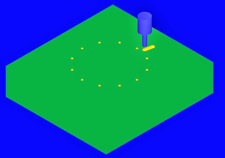
| On to the 0.5" pocketing |
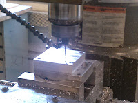 |
| Peck drill for ejection pins |
 |
| That's one truly broken tool bit |
 |
| Elyud got chips all under his shoes for all his troubles |
 |
| Daivon is clearly unhappy about it! |
But after two broken tool bits, one complete redo and lots and lots of laughter, we finished both our molds and they look as lovely as ever!!!
 |
| Finally a beautifully completed core mold |
 |
| Just as beautiful cavity mold |


No comments:
Post a Comment